


Specifications developed by the design professional(s) provide the contractor with the written descriptions of materials, construction systems, quality of materials, and level of workmanship. The specifications function as:
■ A description of the proposed work for bid compliance
■ A technical rule book during manufacturing and construction
■ A legal instrument that can be used in a court of law
The bound volume of the specifications is generally represented in the following sequence, particularly for large projects:
- Invitation to bid
- Instructions to bidders
- Bid (proposal) form
- Client-contractor agreement form
- Bid bond form
- Performance bonds forms
- Alternates
- General conditions of the contract
- Supplementary conditions of the contract
- Technical trade sections
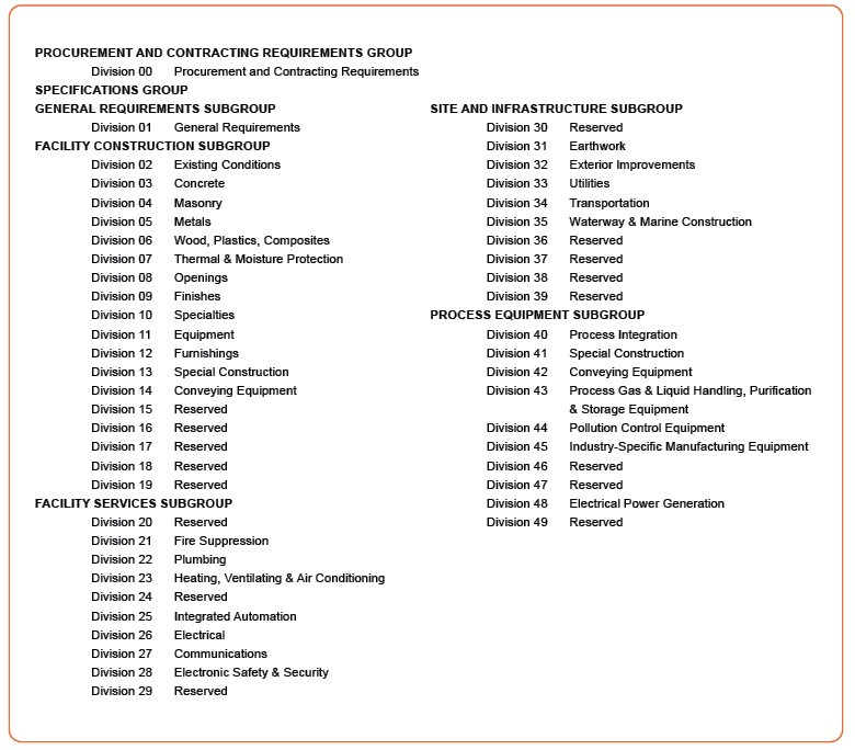
An industry organization, the Construction Specifications Institute (CSI), has developed an organization format called the MasterFormat. The MasterFormat has been widely adopted in the industry. This format breaks down the technical specifications of the project into standard divisions that aid in organizing construction materials and processes. It also helps construction by simplifying project information using standardized categories. Figure 11 shows the MasterFormat 2004 Division Numbers and Titles.
The cost estimate is based on the drawings and specifications. The modular building contractor is responsible for everything contained in the specifications as well as the drawings. There is a tendency among estimators to simply skim over the specifications. Reading the average specifications is time consuming, but many important items are mentioned only in the specifications and not in the drawings. There is no question that skimming the specifications is risky. Either the estimates will be too high due to higher contingencies or too low due to missing some items in the project.
■ Specifications determine the quality of the materials
■ Many errors have been made by skimming the specifications
■ Take note of anything that affects the cost of the project
■ Items to be included:
» Services provided by the contractor
» Specified names of manufacturers
» Unusual performance requirements & materials
» Items that affect organization of the estimate (i.e. alternates)
» Special construction phasing requirements
Another important part of a specification is the section format. Each of the divisions of the CSI Masterformat is broken into sections. A section is a unit of work that is grouped with related units of work forming a division. A part is an organizational device to divide a section into three distinct categories of related information. The three parts are:
■ Part 1 – General
■ Part 2 – Products
■ Part 3 – Execution
Part 1 covers those general areas of concern which relate to the work and which define the general administrative and technical requirements specific to a particular section.
- Work included
- Related work (in other sections)
- System description
- Quality assurance
- References
- Submittals
- Delivery, storage, and handling
- Project conditions
- Sequencing/scheduling
- Alternatives
- Allowances
- Unit prices
- Warranties
Note that all 13 of these items do not have to be used. Use is only as required. This also applies to the items in Part 2 and Part 3.
Part 2 defines in detail the acceptable equipment, materials, fixtures, mixes, and fabrications, (i.e., product items) to be incorporated into the work.
- Equipment
- Materials
- Fixtures
- Mixes
- Fabrication
Part 3 describes in detail the manner in which the items covered in Part 2 are to be incorporated into the work.
- Inspection
- Preparation
- Installation/application/erection
- Field quality control
- Protection
- Adjusting and cleaning
- Extra stock/spare parts
- Schedules
See an abbreviated example of a typical exterior non-load-bearing curtain wall framing specification that follows. Page formats are similar in most cases but may vary depending on the architect’s/engineer’s preference. A page format has three basic objectives:
- To present clear but reasonable maximum density of text.
- To provide page uniformity throughout the Project Manual.
- To provide a format for preparation by typewriter, word processor, or computer in the architect’s/ engineer’s office. You will see many versions which will fit the preparer’s criteria.
SECTION 05400 – COLD-FORMED METAL FRAMING
PART 1 GENERAL
1.1 RELATED DOCUMENTS
A. Drawings and general provisions of the Contract, including General and Supplementary Conditions and Division 1 Specification Sections, apply to this section.
1.2 SUMMARY
A. Work required under this section shall include exterior non-load-bearing curtain-wall framing.
1.3 QUALITY ASSURANCE
A. Testing Agency Qualifications: An independent testing agency qualified according to ASTM E 329 to conduct the testing indicated, as documented according to ASTM E 329.
B. Welding: Quality procedures and personnel according to AWS D1.1 “Structural Welding Code-Steel” and AWS D1.3 “Structural Welding Code – Sheet Steel”
C. Fire-Test-Response Characteristics: Where metal framing Is part of a fire-resistance-related assembly, provide framing identical to that of assemblies tested for fire resistance per ASTM E 119 by a testing and inspecting agency acceptable to authorities having jurisdiction.
D. Comply with AISI’s “North American Specification for the Design of Cold-Formed Steel Structural Members” and its “Standard for Cold-Formed Steel Framing – General Provisions”.
1.4 SUBMITTALS
A. Shop Drawings: Show layout, spacing, sizes, thicknesses, and types of cold-formed metal framing; fabrication; and fastening and anchorage details, including mechanical fasteners.
B. LEED Submittals:
-
- Credit MR 4.1 and MR 4.2: Product data indicating percentages by weight of postconsumer and post-industrial recycled content for products having recycled content.
- Credit MR 5.1: Identify each regionally manufactured material, including name of manufacturer, address and cost.
C. Mill certificates signed by steel sheet producer or test reports from a qualified independent testing agency indicating steel sheet complies with requirements.
D. Welding certificates for welding procedures and personnel.
1.5 STORAGE OF MATERIALS
A. Store cold-formed metal framing, protect with a waterproof covering against corrosion, and ventilate to avoid condensation.
PART 2 PRODUCTS
2.1 MATERIALS
A. Steel Studs: Manufacturer’s standard C-shaped steel studs, of web depths indicated, punched, with stiffened flanges, complying with ASTM C 955 and as follows:
- Minimum Base-Metal Thickness: 0.0329 inch
- Flange Width: 1-5/8 inches
B. Steel Track: Manufacturer’s standard U-shaped steel track, of web depths indicated, unpunched, with unstiffened flanges, complying with ASTM C 955 and as follows:
- Minimum Base-Metal Thickness: Matching steel studs
- Flange Width: 1-1/4 inches
C. Single Deflection Track: Manufacturer’s single, deep-leg, U-shaped steel track, unpunched, with unstiffened flanges, of web depth to contain studs while allowing free vertical movement, with flanges designed to support horizontal and lateral loads and as follows:
- Minimum Base-Metal Thickness: 0.0428 inch
- Flange Width: 2 inches
D. Double Deflection Track: Manufacturer’s double, deep-leg, U-shaped steel track, consisting of nested inner and outer tracks, unpunched, with unstiffened flanges.
- Outer Track of web depth to allow free vertical movement of inner track, with flanges designed to support horizontal and lateral loads and as follows:
-
- Minimum Base-Metal Thickness: 0.0428 inch
- Flange Width: 2 inches
-
- Inner Track of web depth indicated and as follows
-
- Minimum Base-Metal Thickness: 0.0428 inch
- Flange Width: 3-1/2 inches
-
E. Mechanical Fasteners: Corrosion resistant-coated, self-drilling, self-threading steel drill screws.
F. Power-actuated anchors: Fastener system of type suitable for application indicated, abricated from corrosion-resistant materials, with capability to sustain, without failure, a load equal to 10 times design load, as determined by testing per ASTM E 1190 conducted by a qualified independent testing agency.
2.2 FABRICATION
A. Fabricate cold-formed metal framing and accessories plumb, square, and true to line, and with connections securely fastened, according to referenced AISI’s specifications and standards, manufacturer’s written instructions, and requirements in this section.
PART 3 EXECUTION
3.1 PREPARATION
A. Grout bearing surfaces uniform and level to ensure full contact of bearing flanges or track webs on supporting concrete or masonry construction.
3.2 INSTALLATION
A. Install continuous tracks sized to match studs. Align tracks accurately and securely anchor to supporting structure as indicated.
B. Fasten both flanges of studs to bottom track, unless otherwise indicated. Space studs as indicated or as required to withstand lateral loads.
C. Set studs plumb, except as needed for diagonal bracing or required for nonplumb walls or warped surfaces and similar requirements.
D. Install horizontal bridging in curtain-wall studs, spaced in rows indicated on shop drawings but no more than 54 inches apart. Fasten at each stud intersection.
E. Install miscellaneous framing and connections, including stud kickers, web stiffeners, clip angles, continuous angles, anchors, fasteners, and stud girts, to provide a complete and stable curtain-wall-framing system.